|
|
||
|---|---|---|
| .. | ||
| CAD | ||
| firmware | ||
| pcb | ||
| production | ||
| readme.md | ||
Trigger Pad
Inspiration
My goal with this macropad was to make tasks easier by assigning complex shortcuts to a single button. This improves efficiency and speeds up repetitive tasks. Through this process, I learned a lot about PCB design, component placement, and making trade-offs to create a functional design.
Challenges
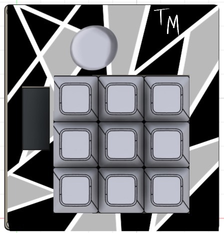
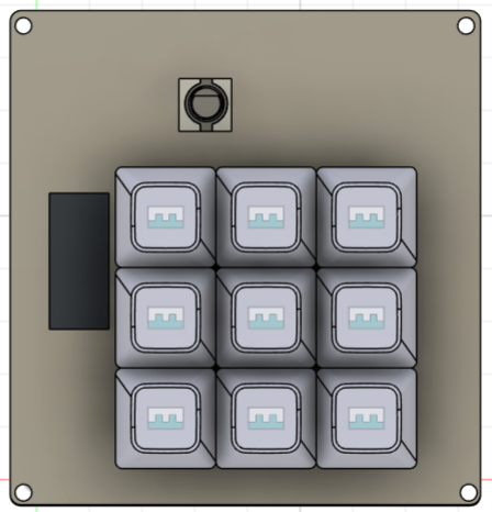
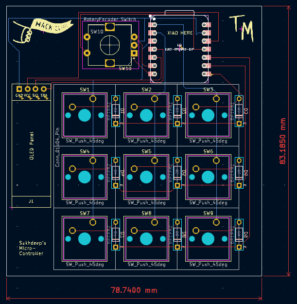
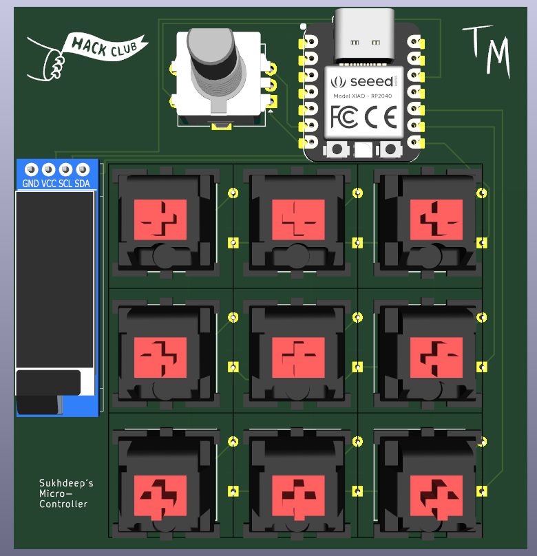
This was my first time creating a pcb and I have to say it was quite an experience. I did encounter a few problems and making many itteration of my macropad, but I finally settled for a design. Originally in my first itteration I wanted to make a 4x4 macropad with 1 rotary encoder and with a OLED display with rgb. Though, soon realized I could not fit all of that into one board. In my next itteration I had a 3x3 macropad with one rotary encoder, an OLED display, with rgb. Although I could fit everything in one board, I had some trouble routing everything with the rgb and even if I had solved that problem the placing of the LEDs was a bit tricky. So finally in my last itteration, I am sticking with a 3x3 macropad with only an OLED display and a rotary encoder! Once I get all the items I will first spraypaint the case to make it look like the one in the first below below then I will make my own custom knob........
Specifications
BOM:
- 1x XIAO RP2040
- 9x Blank DSA Keycaps White
- 4x M3x16 Bolt
- 4x M3 Heatset
- 1x EC11 Rotary encoders
- 0.91 inch OLED display
- 9x Cherry MX Switches
- 9x Through-hole 1N4148 Diodes
- 4xM3 hex nuts
Others:
- QMK Firmware
- Case Top.stl
- Case bottom.stl